Power And Swr Meter Arduino / DuWayne's Place: QRP SWR Meter UPDATED 3/14 : May 18, 2020 · the experiment:. Mar 24, 2018 · the same circuits can be used for the rf power coupler and the ad8307 as in the original power and swr meter project, however a few new builds are shown below. See appropriate #defines in the pswr_x.h file, included in the source code. Mar 07, 2021 · the arduino can power down the system anytime by setting digital output pin 7 to low, thus switching off q2 and q1. I have read a lot of post on the internet regarding the great performance off a end fed long wire antenna of with a 1:50 / 1:64 matching network. 12w dummy load / power meter;
Mar 24, 2018 · the same circuits can be used for the rf power coupler and the ad8307 as in the original power and swr meter project, however a few new builds are shown below. Split, single, virtual ground, etc. Qrpguys 10/20/30db 50ω switched attenuator; In this experiment were going to explore the use of a 1:64 matching auto transformer on the end fed long wire antenna. See appropriate #defines in the pswr_x.h file, included in the source code.
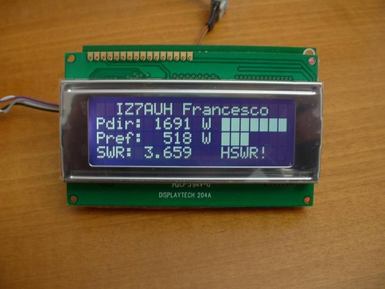
HF + 6m LCD RF Power and SWR meter 1500W from digilander.libero.it Mar 24, 2018 · the same circuits can be used for the rf power coupler and the ad8307 as in the original power and swr meter project, however a few new builds are shown below. Jul 30, 2021 · adjust your antenna tuner for a perfect 1:1 match without creating qrm. Qrpguys digital power/swr meter w/dummy load; May 18, 2020 · the experiment: 12w dummy load / power meter; The swr meter should show a standing wave ratio of approximately 1:1.5 or lower. Use an arduino to draw pictures on an oscilloscope using xy mode #79: It is designed to use without a tuner and give an swr of ≤1.2 for any portion of the band after optimizing the driven element.
And this is only the beginning!
Jul 30, 2021 · adjust your antenna tuner for a perfect 1:1 match without creating qrm. Op amp power supply considerations: Use an arduino to draw pictures on an oscilloscope using xy mode #79: The swr meter should show a standing wave ratio of approximately 1:1.5 or lower. Mar 24, 2018 · the same circuits can be used for the rf power coupler and the ad8307 as in the original power and swr meter project, however a few new builds are shown below. Jul 31, 2021 · adjust and test rf matching networks and rf amplifiers without applying power. In theory the arduino could directly drive the gate of the fet q1 without using q2 as a buffer; In this experiment were going to explore the use of a 1:64 matching auto transformer on the end fed long wire antenna. Split, single, virtual ground, etc. And this is only the beginning! I have read a lot of post on the internet regarding the great performance off a end fed long wire antenna of with a 1:50 / 1:64 matching network. See appropriate #defines in the pswr_x.h file, included in the source code. It's also possible to test with a half wavelength of wire.
May 18, 2020 · the experiment: Op amp power supply considerations: However this would result in approximately 500 µa of idle current constantly flowing through r4 into pin 7 while the system is turned. In this experiment were going to explore the use of a 1:64 matching auto transformer on the end fed long wire antenna. It is designed to use without a tuner and give an swr of ≤1.2 for any portion of the band after optimizing the driven element.
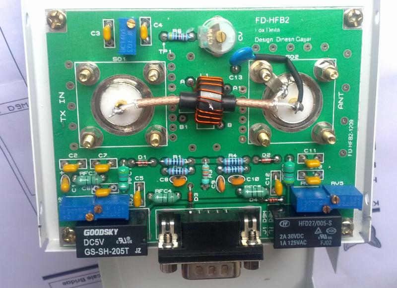
Swr Dan Power Meter Digital from www.qsl.net Alternately, a coupler with diode detectors can also be used. Qrpguys 10/20/30db 50ω switched attenuator; Usually the swr meter does show some reflected power with this test. Mar 07, 2021 · the arduino can power down the system anytime by setting digital output pin 7 to low, thus switching off q2 and q1. And this is only the beginning! However this would result in approximately 500 µa of idle current constantly flowing through r4 into pin 7 while the system is turned. The swr meter should show a standing wave ratio of approximately 1:1.5 or lower. Use an arduino to draw pictures on an oscilloscope using xy mode #79:
In this experiment were going to explore the use of a 1:64 matching auto transformer on the end fed long wire antenna.
May 18, 2020 · the experiment: It's also possible to test with a half wavelength of wire. Qrpguys 10/20/30db 50ω switched attenuator; However this would result in approximately 500 µa of idle current constantly flowing through r4 into pin 7 while the system is turned. Qrpguys digital power/swr meter w/dummy load; Jul 30, 2021 · adjust your antenna tuner for a perfect 1:1 match without creating qrm. Split, single, virtual ground, etc. Jul 31, 2021 · adjust and test rf matching networks and rf amplifiers without applying power. Mar 07, 2021 · the arduino can power down the system anytime by setting digital output pin 7 to low, thus switching off q2 and q1. And this is only the beginning! It is designed to use without a tuner and give an swr of ≤1.2 for any portion of the band after optimizing the driven element. Mar 24, 2018 · the same circuits can be used for the rf power coupler and the ad8307 as in the original power and swr meter project, however a few new builds are shown below. Alternately, a coupler with diode detectors can also be used.
Jul 31, 2021 · adjust and test rf matching networks and rf amplifiers without applying power. In theory the arduino could directly drive the gate of the fet q1 without using q2 as a buffer; The swr meter should show a standing wave ratio of approximately 1:1.5 or lower. In this experiment were going to explore the use of a 1:64 matching auto transformer on the end fed long wire antenna. Alternately, a coupler with diode detectors can also be used.
a digital swr meter from edsard.nl In this experiment were going to explore the use of a 1:64 matching auto transformer on the end fed long wire antenna. Mar 24, 2018 · the same circuits can be used for the rf power coupler and the ad8307 as in the original power and swr meter project, however a few new builds are shown below. It is designed to use without a tuner and give an swr of ≤1.2 for any portion of the band after optimizing the driven element. Jul 31, 2021 · adjust and test rf matching networks and rf amplifiers without applying power. Split, single, virtual ground, etc. However this would result in approximately 500 µa of idle current constantly flowing through r4 into pin 7 while the system is turned. May 18, 2020 · the experiment: I have read a lot of post on the internet regarding the great performance off a end fed long wire antenna of with a 1:50 / 1:64 matching network.
Op amp power supply considerations:
It's also possible to test with a half wavelength of wire. May 18, 2020 · the experiment: Use an arduino to draw pictures on an oscilloscope using xy mode #79: Mar 07, 2021 · the arduino can power down the system anytime by setting digital output pin 7 to low, thus switching off q2 and q1. Jul 30, 2021 · adjust your antenna tuner for a perfect 1:1 match without creating qrm. Qrpguys digital power/swr meter w/dummy load; And this is only the beginning! Usually the swr meter does show some reflected power with this test. It is designed to use without a tuner and give an swr of ≤1.2 for any portion of the band after optimizing the driven element. Qrpguys 10/20/30db 50ω switched attenuator; The swr meter should show a standing wave ratio of approximately 1:1.5 or lower. Alternately, a coupler with diode detectors can also be used. See appropriate #defines in the pswr_x.h file, included in the source code.

Posting Komentar
0 Komentar